Why Copper Thickness Matters in PCB Design
When designing printed circuit boards (PCBs), engineers often focus on trace width, signal integrity, and thermal management. However, one crucial factor that is frequently overlooked is copper thickness. Copper thickness plays a pivotal role in determining the electrical performance, thermal conductivity, and mechanical durability of a PCB.
Choosing the right copper thickness can be challenging, especially when balancing cost, performance, and manufacturing feasibility.
This guide will help you navigate the differences between standard and heavy copper PCBs, offering insights into their applications, challenges, and best practices.

Why Copper Thickness Matters in PCB Design
The Hidden Impact of Copper Thickness on Signal Integrity
Copper thickness directly influences a PCB’s signal integrity, especially in high-speed and high-frequency applications. As signal frequencies increase, the skin effect becomes more pronounced, forcing current to travel along the conductor’s surface. In thicker copper traces, this effect can result in higher resistance and signal attenuation.
Example: A high-speed PCB designed for 5G communication experienced signal loss and distortion when using 4 oz copper. According to a study published in IEEE Xplore, increased copper thickness can lead to higher resistance and signal degradation in frequencies above 5 GHz due to the skin effect.
Why You Can’t Ignore Copper Thickness in High-Power Applications
Copper thickness is directly linked to a PCB’s ability to handle high current loads. In power electronics, choosing the wrong thickness can result in voltage drops, overheating, and even circuit failure.
- Standard Copper (1 oz): Suitable for low-current applications such as consumer electronics. Current capacity: up to 1.2 A per mm².
- Heavy Copper (3 oz or more): Ideal for high-power circuits like inverters, motor drivers, and power distribution units. Current capacity: up to 4.5 A per mm².

Practical Tip:When designing high-current PCBs, always calculate the current density according to IPC-2221 standards. Use a 4 oz copper layer for currents exceeding 5A to ensure reliable performance.
Standard vs Heavy Copper: Which One Suits Your Application?
Practical Use Cases for Standard Copper
For most consumer electronics and low-power devices, standard copper thickness (1 oz or 2 oz) suffices. These applications include:
- Smartphones and Tablets: Low current requirements with a focus on signal clarity.
- Wearable Devices: Lightweight, compact designs with minimal power consumption.
- Automotive Dashboards: Low-voltage circuits with basic signal processing.
Advantages of Heavy Copper in Power Electronics
Heavy copper PCBs are essential in applications where high current density and thermal management are critical. These boards are prevalent in:
- Power Supply Units (PSUs): Efficient current flow minimizes heat buildup.
- Battery Management Systems (BMS): Heavy copper ensures reliable power distribution.
- Industrial Motor Controllers: Enhanced mechanical robustness against vibrations.
Supporting Data: According to a study by PCBWay, using 4 oz copper reduced the average trace temperature by 20% compared to 2 oz copper under similar load conditions.
Design Insight:For applications requiring both high current capacity and efficient heat dissipation, opt for 4 oz copper on critical power paths and 2 oz copper on control layers to balance cost and performance.
Comparing Standard and Heavy Copper: Advantages and Disadvantages
Standard Copper vs Heavy Copper: Key Differences
| Feature | Standard Copper (1-2 oz) | Heavy Copper (3-6 oz) |
|---|---|---|
| Cost | Lower, suitable for consumer electronics | Higher, due to complex manufacturing |
| Signal Integrity | Good for low-frequency applications | Can cause signal loss at high frequencies |
| Heat Dissipation | Limited, prone to overheating | Excellent, suitable for high-power applications |
| Mechanical Strength | Moderate, flexible | High, more rigid, ideal for industrial environments |
| Manufacturing Complexity | Simple etching process | Requires advanced plating and etching techniques |
Practical Tip:
For high-current applications such as power inverters or motor controllers, opt for heavy copper (4 oz or more) to enhance thermal management and mechanical robustness.
Real-Life Applications: Successes and Failures
Heavy Copper in 5G Power Amplifiers: A Success Story
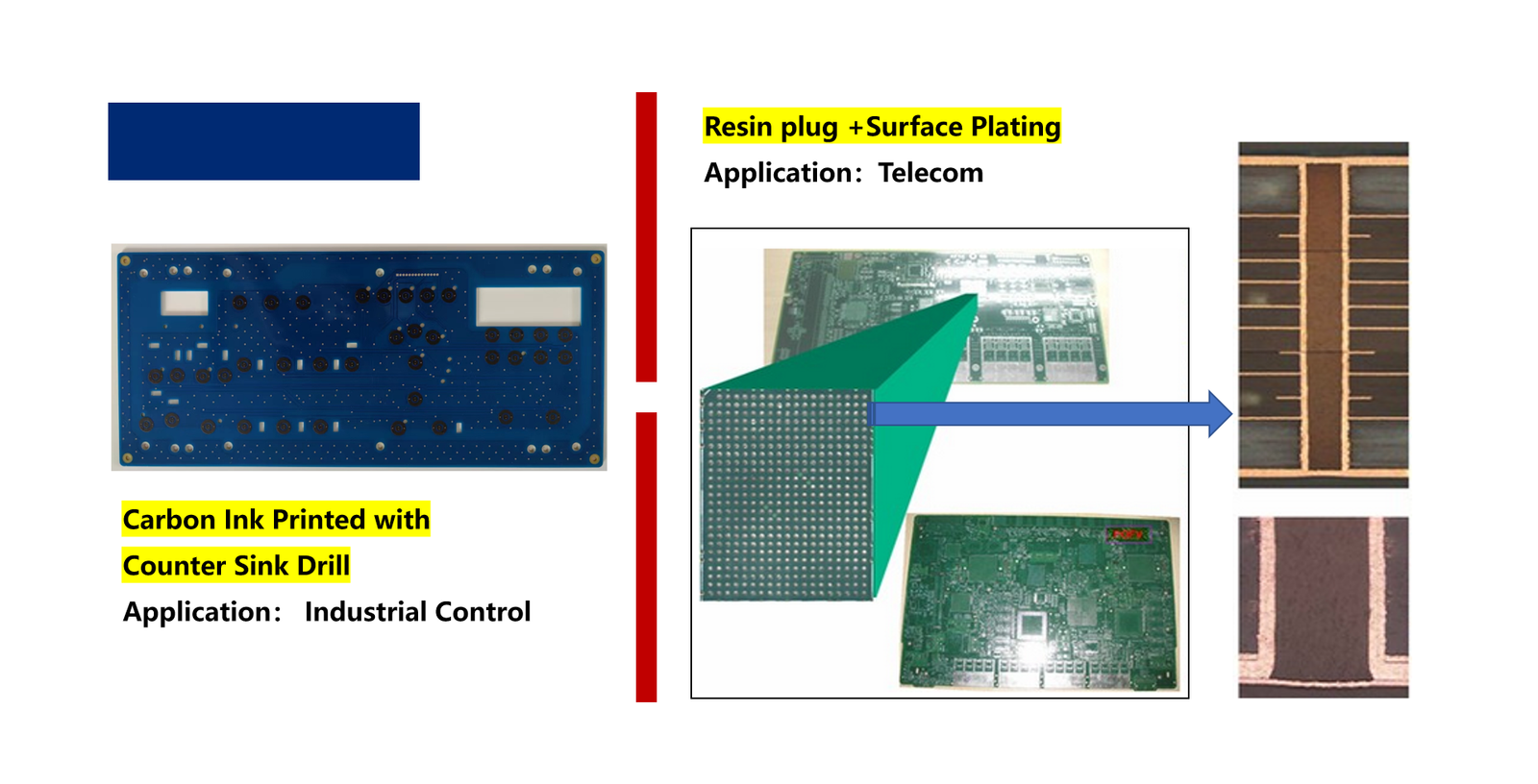
With the rise of 5G networks, maintaining signal integrity and power stability in RF circuits has become increasingly important. A major challenge faced by telecom manufacturers was the rapid degradation of signal quality due to inadequate copper thickness.
Problem: A 5G amplifier module using 2 oz copper faced signal distortion and excessive heat during peak transmission.
Solution: Engineers upgraded to 4 oz copper on power layers, maintaining 2 oz copper on signal traces. This hybrid approach resulted in:
- 30% better heat dissipation.
- Stable voltage regulation under continuous high-power conditions.
Failure Example: Standard Copper in High-Power Motor Control
Motor control systems require reliable power handling, but using the wrong copper thickness can result in severe performance issues. One industrial PCB manufacturer learned this the hard way.
Problem: A motor control PCB using 1 oz copper experienced:
- Trace overheating, leading to insulation breakdown.
- Voltage drops under continuous high-current load.
- Delamination due to thermal expansion.
Root Cause: The use of standard copper in a high-current application led to inadequate thermal management, causing trace deformation.
Solution: Upgrading to 4 oz copper increased current capacity by 150%, while reducing surface temperatures from 90°C to 60°C.
Engineering Insight:
For high-power motor control PCBs, always perform thermal simulation to determine the optimal copper thickness. Use tools like ANSYS HFSS to predict current density and heat distribution.

Design Considerations: Calculating the Right Copper Thickness
Formula for Copper Thickness Calculation
Use the following formula to calculate copper thickness:
Copper Thickness (mil) = (Current Capacity (A) × Trace Width (mil)) / Conductor Material Factor
Example: A high-current PCB for power distribution requires 10 A. With a trace width of 250 mils and a conductor factor of 0.003:
Copper Thickness = (10 × 250) / 0.003 = 833 mils
Therefore, using 4 oz copper would be suitable for this application.
Cost vs Performance: Finding the Balance
Heavy copper significantly increases manufacturing costs, primarily due to:
- Complex electroplating techniques.
- Higher material consumption.
- Extended fabrication time.
Cost-Saving Tip:
For applications requiring both thermal management and high current capacity, combining 4 oz and 2 oz copper in a multi-layer stack-up can reduce costs by 20% while maintaining performance.
Making the Right Choice for Your PCB
Choosing the appropriate copper thickness for your PCB design requires balancing electrical performance, thermal management, and cost efficiency. While heavy copper offers superior current handling and durability, over-specification can lead to unnecessary production costs.
By evaluating the specific requirements of your application and using simulation tools to validate your design, you can make an informed choice that ensures reliability and cost-effectiveness.

For expert guidance on designing high-performance PCBs, reach out to Zhuhai Longyu Technology.