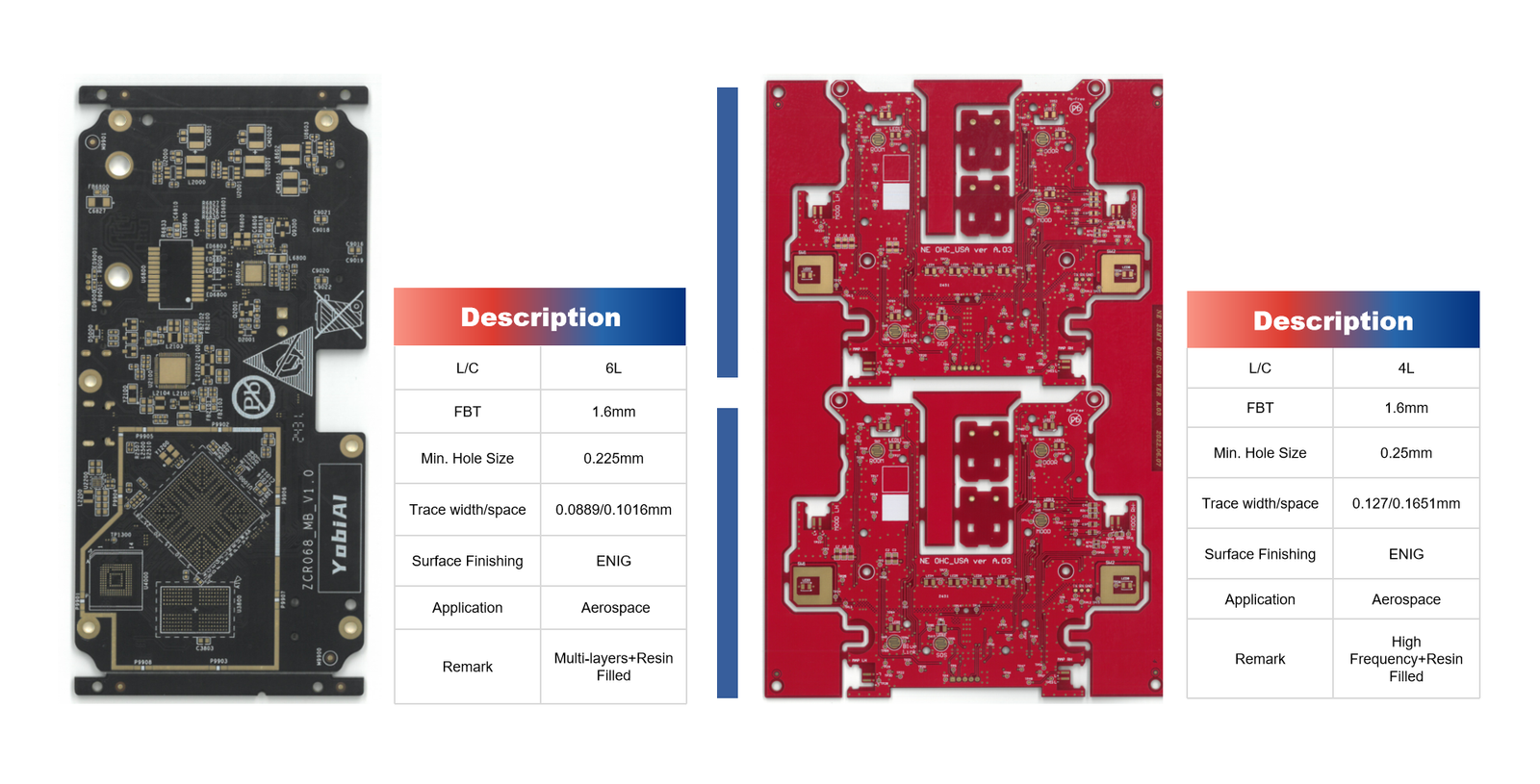
Printed Circuit Boards (PCBs) are the heart of electronic devices, providing a foundation for electrical connections and supporting components.
Ensuring the quality and reliability of PCBs is essential to meet industry standards and guarantee product performance. Inadequate testing can lead to device failures, costly recalls, and loss of brand reputation.
This article explores the most effective methods for PCB testing, offering insights into industry standards and best practices for quality assurance.
1. Electrical Testing Methods: Ensuring Circuit Integrity
Electrical testing verifies the circuit connections and identifies faults such as short circuits, open circuits, and incorrect connections. These tests ensure that the PCB functions correctly as designed, without risking failure during operation.
1.1 Flying Probe Test (FPT)
The Flying Probe Test is a non-contact method that uses movable probes to test the electrical characteristics of the PCB. It is highly flexible and suitable for low- to medium-volume production.
- Advantages: No fixture needed, flexible, ideal for prototypes.
- Disadvantages: Slower speed, not suitable for high-volume production.
1.2 Bed-of-Nails Test (BON)
The Bed-of-Nails Test uses a fixture with numerous pins that contact the PCB at predefined points. It is commonly used in mass production for high-speed testing.
- Advantages: Fast, efficient for mass production.
- Disadvantages: High fixture cost, less adaptable.
| Test Method | Use Case | Advantages | Disadvantages |
|---|---|---|---|
| Flying Probe Test | Prototypes, low-volume | No fixture needed, flexible | Slower speed |
| Bed-of-Nails Test | High-volume production | Fast, efficient | High fixture cost |
For more details, visit the IPC Official Website.
 2. Mechanical Testing Methods: Guaranteeing Structural Robustness
Mechanical testing ensures that PCBs can withstand physical stress and environmental conditions without damage. This testing is crucial for applications in automotive, aerospace, and industrial environments.
2.1 Bend and Warp Testing
Bending tests assess a PCB’s ability to resist physical deformation. During testing, a controlled force is applied to evaluate the board’s mechanical resilience.
2.2 Vibration Testing
Vibration testing simulates real-world conditions by subjecting PCBs to oscillatory motion. This test identifies potential failures in solder joints and component mountings.

3. Thermal Testing Procedures: Assuring Performance Under Extreme Conditions
Thermal testing ensures PCBs perform reliably under varying temperature conditions. This testing is critical for devices operating in harsh environments, such as automotive electronics and industrial control systems.
3.1 Thermal Shock Testing
PCBs are subjected to rapid temperature changes to assess their ability to withstand thermal expansion and contraction without cracking or delamination. Refer to the IPC-9701 Standards for detailed guidelines.
3.2 Reflow Soldering Tests
This test evaluates how well PCBs handle high temperatures during soldering. Issues such as warping and delamination are identified.
4. Chemical and Material Testing: Ensuring Surface Quality and Reliability
Chemical testing validates the surface integrity of PCBs, ensuring that they are free from contaminants and have adequate coating thickness for protection against oxidation and corrosion.
4.1 Ionic Contamination Testing
This test measures the level of ionic residues that may lead to corrosion. Using methods such as Resistivity of Solvent Extract (ROSE) ensures cleanliness levels meet industry standards.
4.2 Surface Finish Thickness Measurement
Techniques like X-ray Fluorescence (XRF) assess the coating thickness of solder masks and metallic finishes to ensure consistent solderability.
5. Reliability and Compliance Standards: Meeting Industry Requirements
Ensuring compliance with industry standards enhances product reliability and customer confidence. The following standards and methods are critical for achieving robust PCB quality assurance.
5.1 Statistical Process Control (SPC)
SPC techniques monitor production processes to detect variations and ensure consistent quality. Visit IPC Standards for more details.
5.2 Failure Mode and Effects Analysis (FMEA)
FMEA identifies potential failure points and assesses their impact, allowing proactive risk management during the design and manufacturing phases.
Achieving Reliable PCB Performance Through Comprehensive Testing
Testing PCBs for quality assurance is not merely a routine process but a critical step in ensuring reliability and compliance. Employing a combination of electrical, mechanical, thermal, chemical, and compliance testing guarantees that PCBs meet industry standards and perform reliably across various applications.

If you are looking to enhance your PCB testing processes or need expert consultation on quality assurance, contact us today and ensure your products meet the highest industry standards!