In high-speed PCB design, maintaining signal integrity is crucial. As signal frequencies and data rates increase, even minor impedance mismatches can lead to significant signal degradation, including reflection, crosstalk, and data loss.
Therefore, achieving consistent impedance control is essential for ensuring optimal performance in modern electronic applications.
At Zhuhai Longyu Technology Co., Ltd., we understand the importance of precise impedance control. As a global one-stop PCB service provider, we leverage advanced manufacturing processes and high-quality materials to deliver reliable PCBs for industries like telecommunications, automotive, and consumer electronics.
Understanding PCB Impedance Control: Key Concepts and Challenges
PCB impedance control involves maintaining consistent electrical characteristics along transmission lines, especially critical in high-frequency and high-speed applications.
What is Controlled Impedance?
Controlled impedance ensures that transmission lines maintain a consistent resistance to AC signals. This is particularly important for high-frequency signals, where impedance mismatches can cause data errors.
Reference: To understand more about controlled impedance and high-speed design, see IPC-2141A: Controlled Impedance Circuit Boards and High-Speed Logic Design.

Why Does It Matter?
In high-speed applications, even minor impedance inconsistencies can result in:
- Signal Reflection: Disrupting data transmission.
- Signal Attenuation: Reducing signal strength.
- Crosstalk: Causing interference between traces.
- Timing Jitter: Affecting data synchronization.
For more insights on high-speed PCB design guidelines, visit Altium Resources – High-Speed Design.
Why Impedance Control Matters in High-Speed and RF PCB Design
As signal speeds increase, issues related to uncontrolled impedance become more pronounced. Uncontrolled impedance can cause:
Understanding Signal Reflection: Causes and Solutions
When signals encounter a sudden change in impedance, part of the signal energy reflects back towards the source, causing distortion. This reflection can disrupt data transmission, especially in high-speed interfaces like PCIe and Ethernet.
Industry Standard: For a detailed standard on PCB design practices, refer to IPC-2221B: Generic Standard on Printed Board Design.
Minimizing Signal Attenuation in High-Speed Designs
High-speed signals weaken over long distances if impedance is not controlled. Selecting appropriate materials like Rogers 4350B with stable dielectric properties can significantly reduce attenuation.
Avoiding Crosstalk in High-Speed PCB Layouts
High-speed signals can induce voltage in nearby traces, causing interference known as crosstalk. By maintaining controlled impedance and using proper shielding techniques, crosstalk can be significantly reduced.
Solving Timing Jitter Issues in High-Frequency Circuits
Timing jitter occurs when signal edges deviate from their expected positions. Using controlled impedance helps maintain waveform integrity, reducing timing errors in high-speed applications.
How to Specify Your PCB Impedance Requirements to Manufacturers
Give Your Fabricator a Stackup Table: Tips and Best Practices
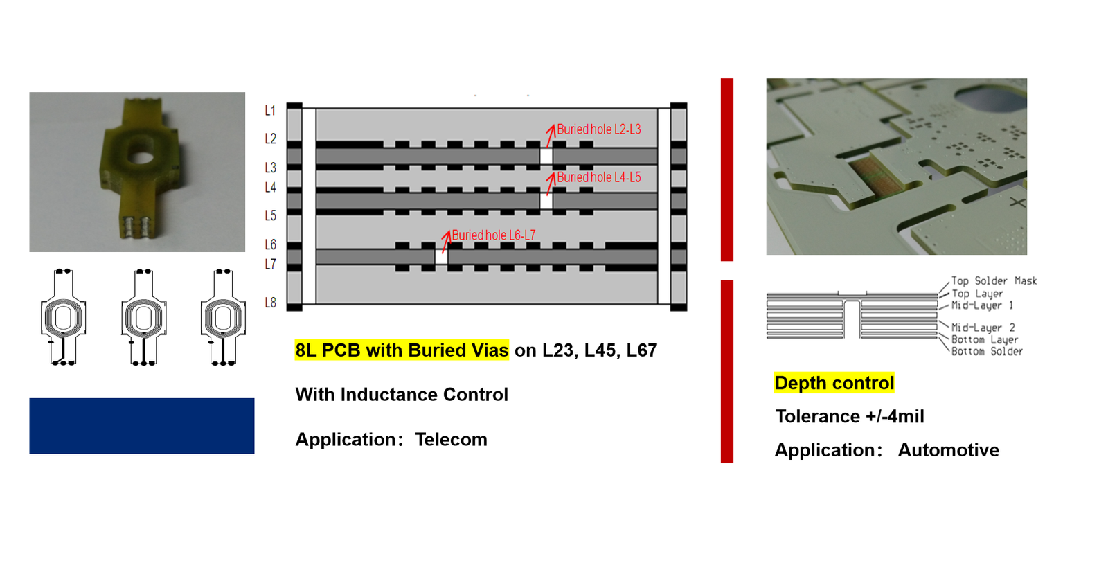
A detailed stackup table is essential to communicate layer structure, material type, and impedance requirements.
Reference: To learn more about optimized stack-up configurations, see PCB Stack-Up Design for Controlled Impedance – IEEE Xplore.
Specify Impedance in Your Fab Notes: Essential Guidelines
Fab notes should contain detailed instructions about impedance control:
- “Maintain a differential impedance of 100Ω ±5% on all high-speed signal pairs.”
- “Use Rogers 4350B for RF signal layers to maintain consistent Dk.”
Make an Impedance Table: Accurate Data for Reliable Manufacturing
An impedance table clearly outlines the desired impedance for different signal types:
| Signal Type | Trace Width | Spacing | Impedance (Ω) | Tolerance |
|---|---|---|---|---|
| Differential Pair | 0.10 mm | 0.20 mm | 100 | ±5% |
| Single-ended Line | 0.15 mm | N/A | 50 | ±10% |
Include Impedance in an SOW: Ensuring Consistency and Quality
Including impedance specifications in a Statement of Work (SOW) formalizes quality expectations and testing protocols. For more on TDR techniques, visit Keysight Technologies – TDR Basics.
Conclusion: Ensuring Reliable High-Speed PCB Design
Maintaining impedance control is vital for high-speed PCB design, as it directly impacts signal quality and system reliability. By carefully planning stack-up, material selection, and testing procedures, engineers can mitigate risks associated with signal integrity.
At Zhuhai Longyu Technology Co., Ltd., we leverage our expertise in high-speed PCB manufacturing to deliver reliable, high-performance solutions.
Contact Zhuhai Longyu Technology for expert advice on designing impedance-controlled PCBs for your next high-speed project.